Pre-order Cence HV, our fault-managed power system here


March 27, 2026
It’s 3 PM on a cold Tuesday in an ISO 5 pharmaceutical filling suite. A single luminaire flickers and dies.
How hard could it be to fix one light?
In a cleanroom, the answer might surprise you.

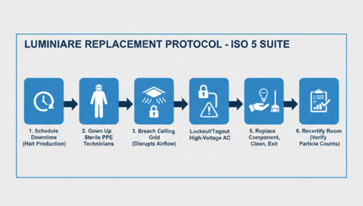
In a commercial office, how this gets fixed is completely different from how this gets done in a cleanroom. In a cleanroom, it is a non-conformance event that triggers a cascade nobody wants to deal with. To repair that single fixture, facilities teams must initiate a protocol that looks like:
1. Scheduledowntime (halting production)
2. Gown uptechnicians in full sterile PPE (Personal Protective Equipment)
3. Breach theceiling grid, potentially disrupting the pressure and laminar flow
4. Lockout/Tagout(LOTO) high-voltage AC circuits
5. Replace thecomponent, clean the area, and exit.
6. Recertify the room to ensure particle counts have returned to acceptable limits before production resumes.
And all of this was triggered not by a system-wide failure, but by a single electronic component inside one lighting fixture.
Facility managers naturally prioritize HVAC efficiency in cleanrooms and for good reason, given that air handling can account for up to 60% of a facility’s energy consumption. But there’s a less visible culprit quietly draining budgets: the maintenance architecture of the lighting system.
Although lighting represents only a modest share of energy use, the way it’s installed can turn routine maintenance into a major expense. It’s a classic case of looking for lost keys under the streetlight, not because that’s where they were dropped, but because that’s where the light is. Too often, teams focus on fixture performance and compliance while overlooking the long-term implications of embedding electronics in sealed enclosures within hard-to-reach ceilings.
By placing failure-prone components inside the cleanroom ceiling, the very design of the system builds downtime and cost into the facility’s lifecycle.
Before we solve the problem, let’s understand why cleanrooms are different from any other lit environment.
The concept of contamination control has deep roots in medicine. However, the modern cleanroom (the laminar flow environment we rely on today) was an invention of the Cold War era.
In 1960, Willis Whitfield, a physicist at Sandia National Laboratories, revolutionized the industry. Before Whitfield, cleanrooms struggled with particle management. Air was simply scrubbed, sure, but turbulence often trapped contaminants in dead zones. Whitfield’s breakthrough? Air entered space in a unidirectional stream (laminar airflow)and exited through the floor, sweeping particles away instantly.
This breakthrough enabled NASA to sterilize spacecraft components and allowed the semi conductor industry to shrink microchips to sizes previously thought impossible.
Today, ISO 14644 standards dictate the cleanliness of these spaces. Yet, despite 60 years of advancement in airflow and filtration, the architecture of lighting power has remained stuck in the past. We are still installing lights the same way we do in commercial office buildings while ignoring the fact that a cleanroom is a fundamentally different operating environment.
Before we talk about what’s failing, let’s establish what cleanroom lighting actually needs to do.
Cleanroom lighting refers to specialized, sealed illumination designed to meet strict cleanliness, airflow, and safety standards in controlled environments. It maintains required light levels without introducing particles, heat, or contamination, supporting ISO 14644 and GMP compliance.
Lighting in a cleanroom isn’t just about visibility; it’s acritical component of operational reliability, compliance, and worker comfort.
Cleanroom Lighting vs. Standard Lighting: Key Differences
Cleanroom fixtures are fully enclosed (often hermetically sealed), lighting units that prevent any ingress of dust, bacteria, or air from entering or escaping. Their goal? Maintain environmental control while providing consistent, glare-free illumination.
Cleanroom lighting fixtures are designed to be:
• Dustproof and waterproof.
• Sealed and easy to sanitize.
• Constructed from non-shedding, non-corrosive materials.
They’re not your average office lights; they’re engineered to preserve the integrity of the environment itself.
Fun fact: Lighting fixtures at Kennedy Space Center’s Vehicle Assembly Building are sealed against hypergolic fuel vapors that could ignite from a single spark. Talk about specification pressure.
So, if cleanroom fixtures are so well engineered (gasketed, IP55-rated,constructed from non-shedding stainless steel), why do they fail?
The answer isn’t the fixture. It’s what’s inside it.
The Weak Link: It’s mostly the LED Drivers.
While housing of a cleanroom fixture is built to survive harsh environments, the LED driver. Whether inside or remotely mounted will fail. To understand why drivers fail, we need to look at the underlying physics.
Electronics do not fail randomly; they fail predictably under thermal stress.
According to Arrhenius law, for roughly every 10°C increase in operating temperature, the life expectancy of electronic component can be reduced by nearly half.
LED drivers rely heavily on electrolytic capacitors, and capacitor degradation accelerates rapidly at elevated temperatures. In a sealed IP65cleanroom luminaire, with limited airflow and conversion losses generating internal heat, the driver operates in one of the worst possible thermal environments.
The result is not just shorter component life. It is an unpredictable maintenance event embedded inside the clean room ceiling.
Because humans are the primary source of contamination, entering the cleanroom ceiling to replace a driver triggers a cascading maintenance protocol that can cost thousands of dollars in lost time and labor.
The replacement driver itself may be inexpensive. The operational cost is not. When a predictable electronic failure triggers an expensive contamination protocol, the issue is no longer component cost, but system architecture.
If the failure point is inside the cleanroom, the maintenance event will also occur inside the cleanroom. The logical solution is to relocate the failure point outside the controlled environment.
The most effective way to address cleanroom lighting maintenance is to rethink where power conversion occurs.
Class 2 DC power distribution, defined by NEC Article 725, relocates the primary AC-to-DC conversion stage outside the cleanroom envelope. Instead of performing high-voltage conversion inside every sealed fixture, power is converted in a remote, accessible location and distributed as low-voltage DC.
Depending on fixture design, localized DC regulation may still occur. However, the line-voltage conversion stage, along with its associated heatgeneration and service requirements, is removed from the controlledenvironment.
This shifts the maintenance burden. Serviceable electronics move to utility spaces. The cleanroom ceiling is left with fewer high-risk components.Maintenance exposure decreases because failure no longer requires breaching the controlled space.
Instead of running high-voltage AC to every fixture and converting it to DC at each individual driver, Class 2 systems perform a single, centralized AC-to-DC conversion in a remote, accessible location. Then they distribute safe low-voltage DC power to fixtures or in some cases to DC-to-DC drivers.
Here’s how a traditional AC-at-the-fixture design stacks up against a Class 2 remote DC architecture.
In a Class 2 system, the LED fixture contains only the light source. Driver components are relocated to an accessible hub outside the cleanroom.
• The Maintenance Shift: When a driver inevitably reaches its end of life, a technician walks into a utility closet, swaps a module in a rack, and walks out. No gowning. No ladders. No ceiling breaches. Zero cleanroom downtime.
The removal of the primary AC-to-DC conversion stage from the fixture housing eliminates the leading source of internal thermal stress. While some architectures may retain a small DC-to-DC regulator near the luminaire, the bulk of the heat generation associated with AC-to-DC rectification is moved away from the sensitive LED chips.
• Lowering the operating temperature of the fixture is a proven method for extending the functional life of LEDs and maintaining consistent lumen output. Furthermore, by eliminating the cumulative heat generated by hundreds of AC drivers in the ceiling grid, the sensible heat load within the cleanroom is reduced. This provides a secondary benefit by lowering the energy demand on the facility’s HVAC systems.
Class 2 power is inherently safe because it limits voltage to typically ≤ 60 V DC. This eliminates the need for rigid conduit and heavy-gauge copper to every fixture.
• The Installation Shift: Installation is faster and cleaner. Connections can often be made via simple low-voltage cabling (like plug-and-play connectors) which reduces the risk of generating particulates during installation or future modifications.
The table below breaks down the potential cost for a 4-hour shutdown based on different industry scenarios found in the search results.
These figures highlight why the preventative strategy using low-voltage lighting with remote drivers to avoid a shutdown altogether is so compelling. Avoiding a single 1-hour shutdown could save your operation tens or even hundreds of thousands of dollars.
For technical facility managers and engineers, the goal is compliance and continuity. ISO 14644 classifies cleanrooms by airborne particle concentration, making any maintenance activity that risks contamination a compliance concern. Every maintenance incursion into the ceiling grid is a risk to that compliance.
Class 2 remote power distribution does not eliminate maintenance. It relocates it. By moving serviceable electronics outside the cleanroom envelope, facilities reduce downtime exposure, lower contamination risk, and align lighting infrastructure with the reliability standards cleanrooms demand. In cleanrooms, failure will happen. The question is where you allow it to occur.
Learn more , if you are interested in knowing more about class 2 low-voltage DC power distribution system.
👉 Start your assessment